Vespa1960 VBA 150 |
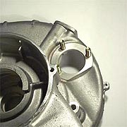
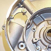
Electric Start:I posted many questions as to what the electrical output of the engine was from the flywheel generator but got no responses. I didn't know if this new type of engine differed from a typical USA P200. We also weren't sure if there was a separate starter motor or if the flywheel generator was just used in reverse. Below are a few shots of the main differences in the casings which allow a small starter motor to drive a toothed flywheel.
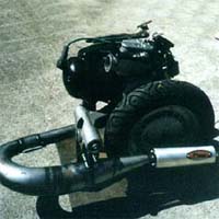
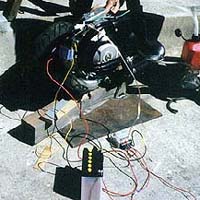
We decided the only way to be sure of the power output was to fire up the engine and measure the power directly from the AC coils and also the DC power directly off the rectifier. We built a small engine stand out of metal which supported the engine through the frame mount and the rear shock mount. I asked a scooter shop in England for the standard battery which turned out to be a 12V-9ah and then picked one up locally. The gasoline was pre-mixed so we didn't have to bother hooking up the oil metering device and gas was connected through a long vertical tube with a funnel on the end. The choke was locked open for starting with a screwdriver and a coat hanger worked to pull the throttle.
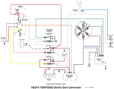
It is a thing of beauty to touch an end of a roughly rigged wiring loom to a battery and hear the electric start kick it to life after years of only knowing kick start P200 engines. It really cranked and the engine started right away. This system will use an automotive relay in the final version (see below). We measured about 2.5 amps directly off the AC lighting coils at an idle which increased to just over 5 amps as the RPMs increased. This seems to be the top limit of the engine as it reached this figure by about an estimated 2000 - 2500 RPM and then as the revs increased the voltage remained constant. This means the brightest bulb we can use in the headlight is a 12V 60/60 watt halogen (if they exist). The rectifier that is specific for an electric start engine was a different story and limited the power to 2.5 amps DC regardless of the revs. This meant that we could not run both the rear light and headlight directly off the battery as the draw would be more than the battery could be recharged. So the final step is to re-wire the bike so it does everything I want it to, but still uses the stock right hand electrical switch. We decided on the following set-up:
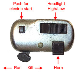
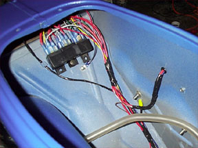
We thought about using the three position run/kill switch to also allow for an electric start only position so that once flipped fully to the left it would only run and not have the possibility of engaging the starter motor by mistake. Eventually we decided that even with gloves on the starter switch is far enough away from the others to be safe. Automotive relays are used to activate the ignition circuit and taillight, the horn, and the electric start. Relays are used because the amount of power that would have to be run through the handlebar switch when starting the bike would fry the old 6V switch. When low current 12V power is put into the relay it triggers a larger switch which can handle the current straight off the battery to power the horn and electric start. These relays are available at any automotive store or Radio Shack and cost about $5 each. They fit in the space behind the fuel tank where the top of the rear shock is connected (inside the frame) as shown below
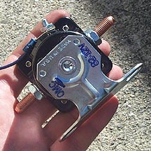
Note Feb 2002 - We managed to fry the 30 amp automotive relay we used in the electric start system after only a couple of months of use. The second time round we have installed a solenoid type relay off a Ford car (about $15.00 from Kragen Auto Parts - part #PA 6772438) - see below:
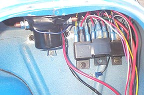
Fords are handy because the solenoid starter relay is separate from the starter motor...and it is 12V so it will work nicley. A motorcyle starter relay is also a good choice and can be bought from any local motorcycle shop. Below is a shot of the main ignition, horn, and starter switch over relay, along with the new solenoid relay beside them. They all managed to fit under the seat.
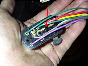
The final step in converting the electrical system is to run through the original switch is to break the power bar on the rear of the switch and solder a new lead to it. While this may sound a little weird it is easy to do and is noted where in the diagram at the bottom of this page. It is shown arrowed below with the new wiring loom.
Next Section --> |
||||||||||||||||||