|
 |
 |
 |
 |
 |
 |
||||||||||||
ElectricalPoints Timing |
Points TimingTiming a points bike is pretty easy but you'll need a few specialized tools to do the job right. Some of these can be made pretty easily and inexpensively and will save you from a headache later on. You'll need:
All the pictures in this section are off a various Vespas but the idea should translate into any points Vespa or Lambretta engine. There are three basic things that need to occur to set the timing correctly:
We'll start with seting the firing point which is figured out by first locating the point at whcih the piston has reacehed the absolute top of its stroke. This can be done with a degree disk or a dial guage. This method shows the degree disk which involves less specialized tools.
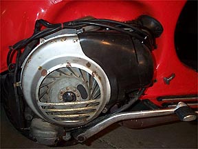
The first step is to remove the right hand side engine cowl to gain access to the motor. Remove the 4 flathead screws that hold the sheet metal flywheel cover to the main casing.
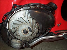
Once the flywheel cover is gone, remove the plastic cap over the central nut. I always use a magnet to hold the degree disk in place, and since aluminum isn't magnetic, I use one on to the end of the crank shaft.
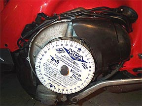
With the degree disk in place you can now start the process to find top dead center (TDC). You may need to cut some access holes in the degree disk face so that you can reach the inspection hole in the flywheel.
Next you need to make a pointer. An easy way to do this is cut about a 2-3" length of wire or an old coat hanger and bend it a hoop in one end. Bend the other end so that when it is mounted to the casing with a fan cowl screw, it will point accurately to the timing disk (see above).
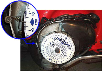
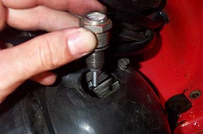
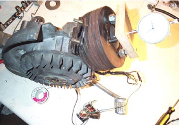
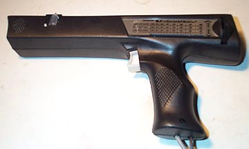
Remove the spark plug and fit the TDC tool carefully. Fully torque it down as if it were the actual spark plug. Depending on where your piston is in the bore, the flywheel may move slightly as you install the tool. The idea behind this tool is that as you rotate the flywheel by hand, the piston will not be able to reach TDC because of the bolt in the tool. Once it hits, if you back it off until it hits again you will know the total amount of degrees between the two points which can give you TDC with a simple calculation. See the next image for a better visual guide.
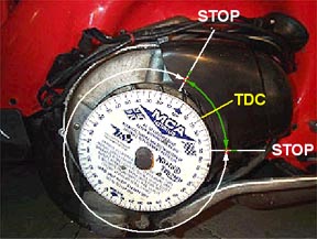
Once the TDC tool is in place turn the flywheel by hand clockwise until it stops against the tool. This is the upper "stop" in the picture above. Remove and replace the timing disk so that the pointer is at zero degrees when the piston is against this stop. From this point on if the degree disk slips or moves in any way you will have to start over, It is very important that this procedure starts from zero when the piston is at the stop. Now slowly turn the flywheel anti-clockwise until it stops again on the lower "stop" in the picture above. Make a note of how many degrees the flywheel has turned between the two stops (represented by the white arc above). Take this number and subtract it from 360 which is the full rotation of the flywheel. This will give you the degrees that the flywheel cannot travel because of the TDC tool (represented with the green arc above). Divide this amount by two (represented by the yellow line above) and the result is the amount of degrees clockwise past the zero on the degree disk to reach TDC. Remove the TDC tool and turn your
flywheel until the zero mark and your wire pointer line up. Now turn
the flywheel clockwise by the result of your calculations. When it
reaches this point you can do one of the following to mark TDC:
Now that you know TDC you can determine
where the bike should fire. All timing points are given by degrees
before top dead center or BTDC. Have a look at the model pages
(Lambretta)(Vespa) and determine how many degrees BTDC is required for
your scooter make and model. Once you have the correct timing degrees
BTDC (we'll use 18 BTDC for an example), line up your marks so that the
motor is at top dead center and place the timing disk and pointer so
that they read 0 degrees. All Vespa and all but one Lambretta motors
rotate clockwise when looking at the flywheel, so you'll need to rotate
the flywheel 18 degrees counterclockwise and this will be the point
where the spark should fire.
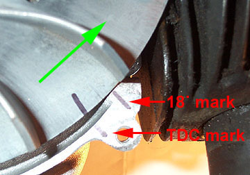
Make another mark on the casing, so that
the new mark aligns with the mark you previously scribed on the
flywheel. If you can it is also handy to mark "18" on the second mark
as timing might need to be changed if you make aftermarket
modifications and this way you'll always know that the mark is only for
a timing of 18 BTDC. Since the piston and flywheel are always
statically connected these lines will always be accurate for when the
motor needs to fire. Setting the points gap:
The gap is the distance between the
faces of the points as they open. If the gap is too large or too small
the motor will run badly. The correct gap for most Vespas is 0.30mm to
0.50mm and can only be measured with the flywheel in place. Check the
model listings just in case your specific model is different. To start,
pull out the rubber bung in the flywheel so that you can see the stator
plate. Rotate it around until you see the points as shown in the
picture below
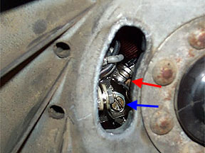
Looking through the inspection hole
you'll see the points (marked with the red arrow above). Look at the
points as you move the flywheel back and forth and you will see that
they open just slightly. There is also a large screw (blue arrow) which
is used to release the points for adjusting. On some models there is
either a place where you can use a screwdriver to carefully lever the
points apart or an eccentric small screwhead which will change the gap.
Using a feeler gauge select a 0.35mm
thickness and rotate the flywheel. You'll start to see the points open
as the window in the flywheel passes over them. At their widest point
apart, stick the feeler gauge directly in between them and then loosen
the large screw (blue arrow in previous picture) until you feel the
points grab the feeler gauge. Then tighten up the large screw and
remove the gauge. The points should stay where they are, separated by
exactly the width of the feeler gauge. If for any reason this doesn't
work or the points have a solid grip on the feeler gauge, you can slide
a small screwdriver in between the two notches on the far edge of the
points (where they overhang the stator edge) and lever them carefully
apart until the feeler gauge is just slightly released.The gap is now
set and you can check the timing. Checking the timing: It is necessary to check the timing of the motor because the points must separate exactly at the BTDC point or the engine will run badly. To do this there are two methods: Statically with use of a small testing circuit or dynamically with a strobe light. Static Method: For years many
people used very thin tobacco rolling paper to check when the points
opened. The idea is you get the points open and place the paper between
them through the inspection hole. Then let them close and put some
tension on the paper by pulling it. Slowly rotate the flywheel and the
paper will slip out when the points separate. This can work if it's your only option but a far more accurate way is to make a small testing circuit which will show you when the points open. You'll need:
Make a small open circuit following the
diagram above (or click it for a PDF). Once you have it made up
disconnect the one red wire on the HT coil (located outside the engine
by the rear shock) and the other contact to the engine casing. If the
HT coil is not connected due to a rebuild you can go directly off the
red wire coming from the stator. Be warned that there is the
possibility of very minor 6V shocks and sparking from doing this -
basically it is less voltage than putting a 9V on your tongue and isn't
really anything to worry about but it may be visible.
Turn the flywheel to the TDC line you made and then turn it counter-clockwise until you see the light bulb get brighter (or is it more dim - I can't remember right now). Either way the light bulb will change brightness at the exact moment the points open. If this matches your scribed mark for 18 BTDC then you are done. If it happens before you reach your mark (i.e. closer to TDC) then you will need to remove the flywheel and rotate the stator slightly counter-clockwise. If it happens after your mark then you will need to remove the flywheel and rotate the stator slightly clockwise. Unfortunately to check the timing each time you will need to refit the flywheel until you get it on the mark, however if you are just refitting for testing purposes only the nut can be finger tight. Just remember to torque it down properly before firing up the motor. Dynamically: The second way to check the timing is get it close by installing the stator aligned with thecasing mark and then fire up the motor and check your flywheel/casing marks with a strobe light.
The strobe will flash every time the spark fires and will show you exactly where the motor is sparking in relation to your marks. The strobe is such a quick burst of light the flywheel will look as if it is not moving and you can easily see if your flywheel is aligning with your casing mark. If it is off then remove the flywheel and move the staor as explained in the static section. |
|||||||||||||||||