1965 Jet BoardEngine |
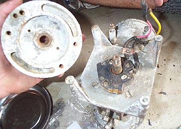
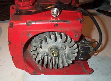
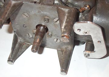
Engine - Ignition SystemThe Jet Board has a very basic ignition system. A one piece pick-up is located underneath the flywheel. It is an FG-5952 system made by Phelon Co. of Massachusetts. Unfortunately there is very little support for an item this old. Even Phelon Co. (which is still in business) was not able to help out with replacement parts. The exterior curved face of the flywheel has two magnets in it whcih pass by a small coil near where the HT coil is mounted to provide AC current to the HT coil and the pick-up. The guy who sold the board to my girlfriend's Dad said they had it running at one point. After removing the flywheel with a two legged puller we realized there was no way that it could have run in its current state. The ignition timing was over 90 degress off the correct point. Below is a shot of the integral stator during the disassembly.
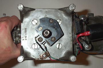
The stator should be mounted with the pick-up facing up (12:00) when the engine is in the board. Below is a shot of the correct position.
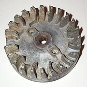
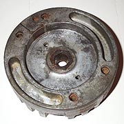
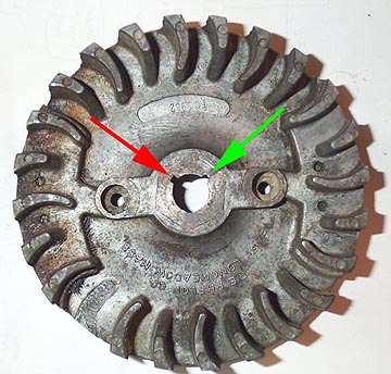
All the wires were replaced with brand new wires, the terminals and spade connectors were sanded down to bare metal and cleaned, and the spark plug was replaced with a new Champion Champion CJ8 spark plug. These plugs are readily available at most lawn mower stores. The flywheel has fins so I assume it must have been a standard part of another small motor which was used out of convenience as a water cooled motor has no need for a finned flywheel. There are two magnets on the perimeter of the flywheel, and a single magnet on the inside face. An external HT coil provides the power behind the spark. Below are shots of the flywheel from both sides in case anyone needs the information. The existing ignition system didn't last long - in fact just about 10 minutes under load before the Jet Board stopped indefinitely (primarily due to the couple of gallons of seawater sloshing over the electrical parts). I scoured the internet and small engine shops to see if anyone had a replacement system with no luck. I then got talking to West Coast Contracting Service in San Francisco and came up with a plan to completely replace all the dead components with working systems that parts are still being made for.
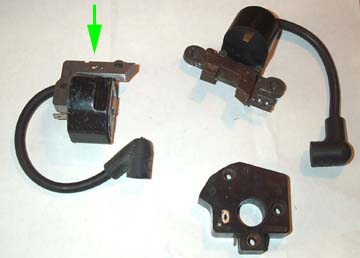
I picked up a dead Homelite XL-88 concrete saw casing and ignition system for a few six packs. The Jet Board system works by creating power with two external magnets around the circumference of the flywheel, but the pick up is located inside the flywheel area, like a stator on a motorcycle. It turns out that the Homelite flywheel has exactly the same magnet configuration on the outside of the flywheel rim. The difference is that the Homelite pick-up/generator system is an all-in-one unit where everything is outside the flywheel and the pick-up is built in to the generating assembly.
So what this means is that the new single coil unit (green arrow) does the same thing as the two previous parts on the right of the image above. The fact that the entire ignition system is outside the flywheel area is good because if anything ever breaks you don't have the to pull the flywheel to fix it. The downside is that the exterior flywheel magnets and the internal pickup point are not at the same location. In the old system the outside magnets only provided power so they could be located anywhere around the flywheel circumference. The pickup metal on the inside if the flywheel is very important in the previous system. It locates the exact time when the spark fires This is important because if it fires too late or too early in the compression stroke, the engine will either not run, or run and then destroy itself. The pick-up metal seemed to be located about 90 degrees anti-clockwise of where the circumference magnets passed the generator coil. If I simply replaced the old coil with the new pick-up/generator coil the timing would have been way off and the motor would not have functioned.
I made a little bracket out of aluminum that holds the new coil on to the existing coil mounting brackets. I drilled the coil mounting holes slightly larger than needed so I could adjsut the air gap between the flywheel and the metal coil parts. I then attached the flywheel and the new Homelite coil and checked that the motor was sparking by removing the plug, grounding it, and spinning the engine using a socket on the flywheel nut chucked up in a drill. With the help of a stobe light I found where the engine was firing which was way off the assumed 12 degrees before top dead center that I was shooting for. The reason I settled on 12 degrees BTDC was due to the fact that most chainsaw manufacturers are between 10 and 14 degrees BTDC so it seemed like a safe bet - we'll see how it works over the long haul (the engine was derived from a chainsaw initially).
The only solution to this is to make a new keyway in the existing flywheel to get the new coil to fire at 12 degreees BTDC. If you want to see how the new keyway was located you can download a PDF of the flywheel layout.
|
|||||||||||