|
 |
 |
 |
 |
 |
 |
||||||||||||
ElectricalElectric Ignition Timing Overview |
Electronic Ignition Timing - OverviewElectronic ignition is a very simple way of providing a spark at the correct time with only a single moving part (the flywheel). It is less complicated than points ignition but the parts are more expensive to build due to their electronic circuitry. There are three main parts to an electronic ignition system:
The Vespa electronic stator is attached to the crankcase and has a hole in the middle which allows the flywheel side of the crank to pass through it. When the flywheel is attached to the crank there is a small key in the crank taper that allows the flywheel to fit on in only one position. This position is statically connected to the piston location at every revolution. Basically this means that the if you marked a point on the casing, noted the piston position, and turned the flywheel 360 degrees the piston will be back in exactly the same position.
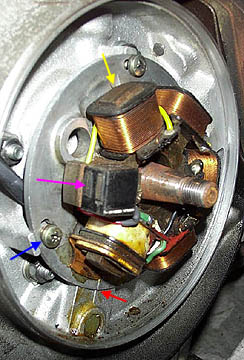
The stator can be seen by removing the flywheel. The stator plate has elongated screw slots so it can rotate by about 10 degrees while remaining connected to the crankcase (blue arrow). These allow the timing to be adjusted by moving the relationship of the pick-up (pink arrow) to the flywheel/piston position. Cast into both the stator and the casing is a line (red arrow) which shows the basic correct alignment of the stator and casings. This is a good starting point for electronic timing, and will be covered in the electronic timing section. Several AC coils are also visible on the stator plate (yellow arrow).
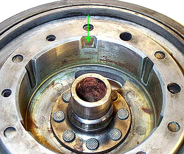
As the flywheel turns, the magnets rotating around the AC coils produce alternating current some of which is routed to the CDI unit while the rest goes to the regulator or rectifier on battery bikes. (A regulator simply limits the AC power to the lights so they don't blow as the RPMs increase. A rectifier does the same thing but also converts AC power to DC for charging a battery). The AC power to the CDI is transformed into DC power and then is stored in a capacitor inside the CDI unit. A capacitor works as a reservoir for DC power during a single engine revolution and can be released and turned into a high voltage charge by the CDI, when triggered by the pick-up coil. All the magnets in the flywheel are separated from each other except for two that overlap in an S type area as can be seen above. The pick-up can sense the disruption in the magnetic field at this point of the flywheel and triggers the high voltage release of the capacitor, down the high tension (HT) lead and makes the plug spark. The reason the spark occurs is that a very high voltage is jumping to ground across a small gap. The beauty of this system is that there are no parts to wear out because nothing actually physically touches another surface. The downside is that there is little to diagnose if there is a fault in the CDI or pick-up and it is usually less of a headache to buy a new one than to determine the problem. Next Section --> |
|||||||||||||||||