|
 |
 |
 |
 |
 |
|||||||||||||
BrakesVespa Rear Brake Change Lambretta Rear Brake Change Vespa Front Brake Change Lambretta Front Brake Change Vespa Disk Brakes Vespa Disk Brake Pads Resources |
Brakes - Replacing Disk PadsThere are two types of disk brake set ups for Vespa scooters. Before a hydraulic disk was standard equipment on the PX models, there was semi-hydraulic version available from Grimeca as an aftermarket kit. The reason it is semi-hydraulic is that there is no master cylinder on the headset, but instead there is a remote reservoir bolted to the fork tube which connects to the handle bar brake lever by a shorter than normal front brake cable. This section will show how to change the brake pads and should be the same for the new five spoke Vespa '98' type hydraulic disk brake which is standard equipment on all new Vespa PXs. Be sure to specify which model you have when ordering pads as I don't have any information if they are the same size for both systems. You will need:
The aftermarket Grimeca kit system comprises of the following parts:
Replacing the padsThe first thing to do is get the bike onto the kickstand and make sure the front wheel is off the ground. Many bikes have bent kickstands which allow the front wheel to sit on the ground. If this is the case with yours, just put a block of wood or a brick under either stand foot to raise the front wheel.
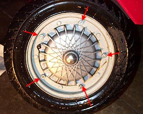
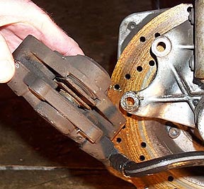
The front wheel rim is removed by loosening the five 13mm nuts around the hub side of the front wheel. Because of the caliper set up the wheel must be removed in order to remove the caliper. This older kit has a different front hub than the newer standard five spoke hub, so yours may differ from the one shown above.
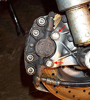
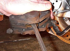
Once the wheel is off you will be able to remove the two bolts noted above which allows the caliper to come free from the hub mount. The hydraulic hose can remain in place because it is a pain to bleed the system if it is removed and will bend enough to allow you to do all the work needed.
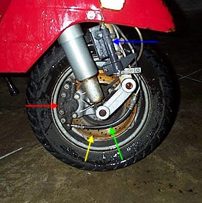
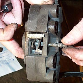
Once the caliper is clear you will be able to see the two pads that grab the rotating disk when the front brake lever is pulled. These ones are very close to having no pad left so both caliper pistons are visible too.
The calipers pistons will need to be spread back to the face of the assembly in order to fit the new pads. The new pads will be much thicker than the ones being replaced so the pistons must be spread in order to fit them both. We used the old pads to protect the pistons from any damage and then carefully wedged a screwdriver between them to force the pistons apart. If they are hard to move they can be lubricated with copper paste but be careful to apply it in such a way that it will not get on to the disk when reinstalled. They should move pretty easily so if you feel you are using excessive force it may make sense to remove the caliper from the hydraulic hose, sort out the problem, and then bleed the system later. I have a page showing how to bleed a similar system here. The principle is the same regardless of where the main reservoir is located.
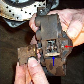
To remove the old pads you will need to remove the plastic cover on the backside of the caliper which allows you to see the anti-rattle spring (blue arrow) and a small retaining pin (red arrow) that passes through the cast hydraulic caliper housing. The plastic cover is just a snap fit on the caliper and a flathead screwdriver works well to pry it off. The retaining pin goes through a hole in the brake pad backing and keeps it in place.
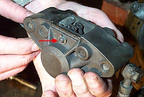
To remove the retaining pin, remove the small circlip at the wheel side of the caliper. We used a small screwdriver to wedge it off by placing it between the pin and the circlip- beware...these things can go flying and are very hard to find.
Once the circlip is removed, pull the pin out. The old brake pads and anti-rattle spring may fall out at this point because the pin is the only thing holding them in place. Note the location and orientation of the anti-rattle spring as it needs to go back in the same position (large side towards the sky when the caliper is in place).
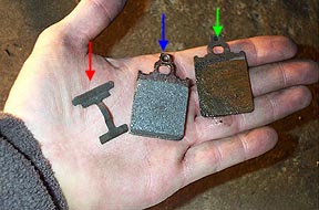
The old disk pad is obviously shown by the green arrow. The new pad is the blue arrow, and the anti-rattle spring (which can be reused is shown with a red arrow.
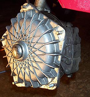
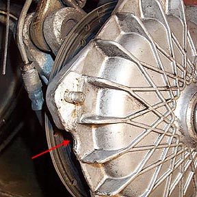
The new pads go into the caliper the same way the old ones came out. The pad surfaces need to be facing each other with the hole in the brake pad backing facing the rear of the caliper, so that the small retaining pin will go through them and hold them in place. When replacing the retaining pin make sure the anti-rattle spring is in the same position it was when removed. Slip the pin through the holes in the pads making sure the pin also secures the anti-rattle spring. Replace the circlip to keep the pin from sliding out, and refit the caliper to the hub. Test the system by rotating the front wheel while the caliper is fully open. There may be slight resistance but this will disappear after less than a mile of riding. The surface of the pads is quite bumpy and needs to be ground down slightly by the rotating disk before they will fully bed in with the disk. The picture above shows a point in the older Grimeca hub that must be aligned with the air valve stem in order to make the wheel rim fit on the hub. Tighten all the 13mm nuts down and test the wheel and brake system before you take it on the road. Next Section --> |
|||||||||||||||||